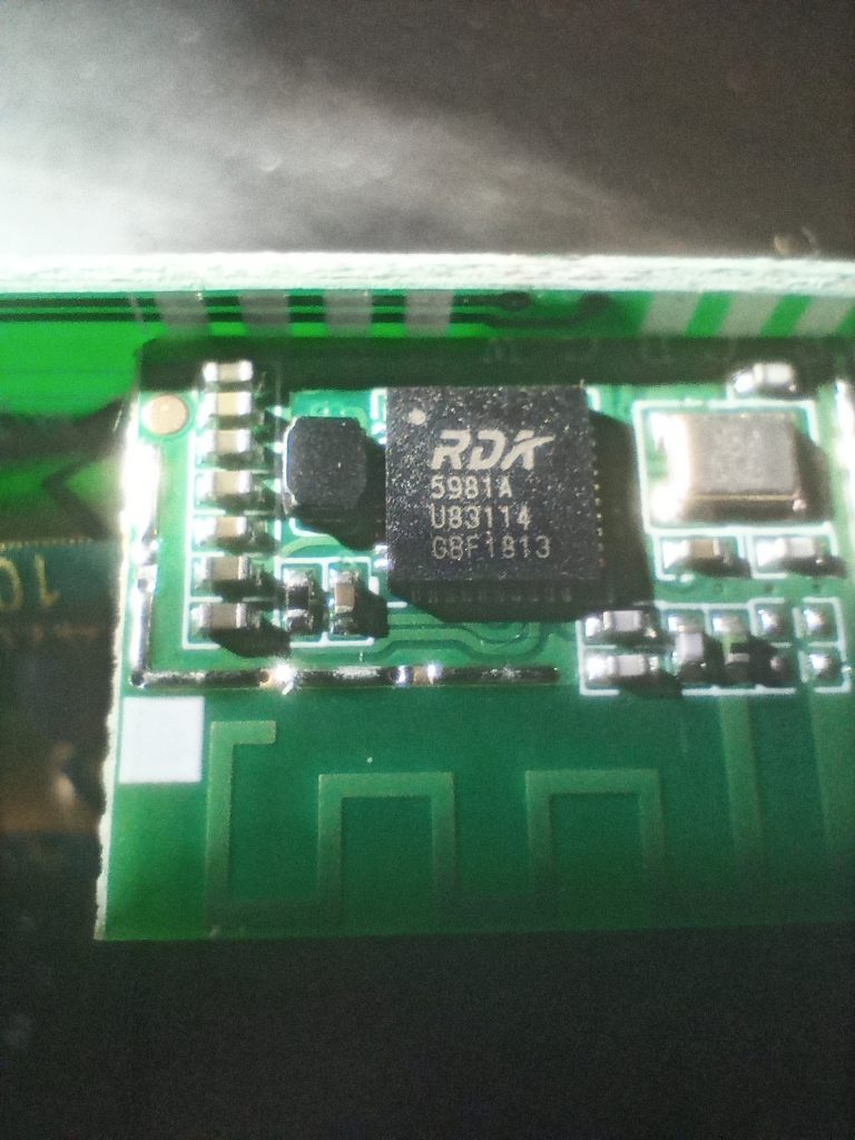
The Owsoo ‘Smart wi-fi ceiling light’ is indeed wireless, but sadly it uses the Unisoc RDA5981 System On A Chip. To my knowledge this chip has not been compromised yet, nor does it have any form of homebrew friendly firmware available for it, like ESPHome or Tasmota. This means that you’re stuck using the supplied firmware, which probably relays all of your data via a ‘cloud’ server in China.
I did find some evidence that Owsoo lights will communicate with MQTT, and you can spoof the foreign server with your own DNS server, but not everyone has access to that. Some may find it easier just to solder on 4 wires and run Home-Assistant or similar. Read on if that’s the case.
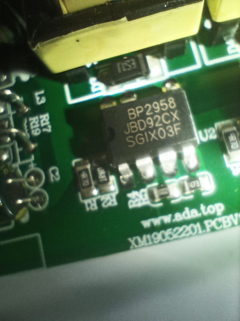
Opening up the light reveals a pair of DIP7 BP2958 chips. I couldn’t find much in English about them, but I suspect they are the BP2958X family from BPSemi. I suspect they might be PWM driver chips for the LEDs. One for the warm white channel and one for the cold white channel.
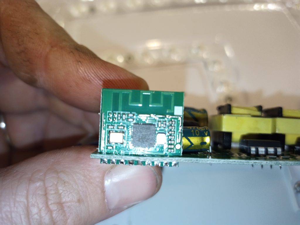
The RDA5981 is on its own PCB, which is soldered on to the main PCB by the edge down at the bottom left. Kind of like an edge connector. Any numbering of pins on this edge connector will be from the left.
Pins 4 and 5 of the SoC edge connector go directly to pin 2 of the respective BP2958 chips, which according to the PDF is ‘PWM’
Pin 5 on the BP2958 chips are connected, and the PDF suggests they are the shared high voltage side, and pins 7 and 8 are the drain side for the LEDs. That explains why on the PCB there is one LED+ and two LED- – it is arranged such that the LEDs consume all the power and the chip merely switches the low side.
The rest of the RDA5981 SoC is labelled as follows
IO03
IO25
IO24
IO23
IO22
RX
TX
Gnd
Vin
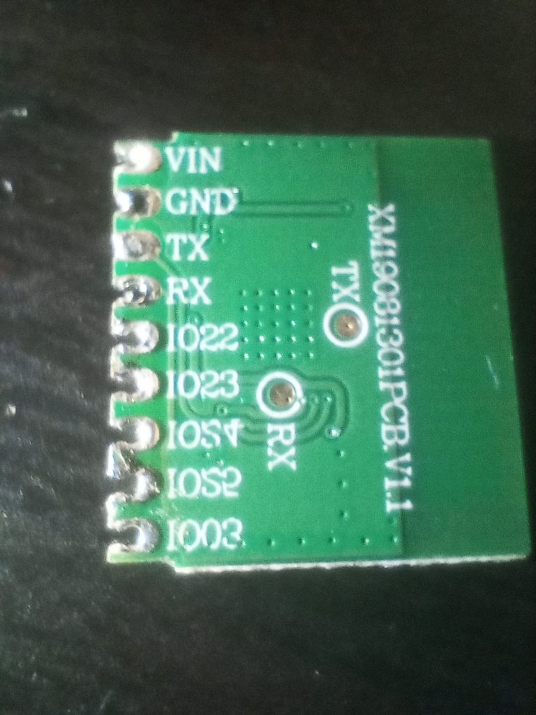
Pins 4 and 5 match up to RX and IO22, so there’s maybe a chance of extracting data out of the UART that might be present on the TX & RX pins. Something for later.
With pin 4 being linked to the ‘left’ driver chip, on my light this operated the cold white channel, leaving pin 5 for the warm white channel.
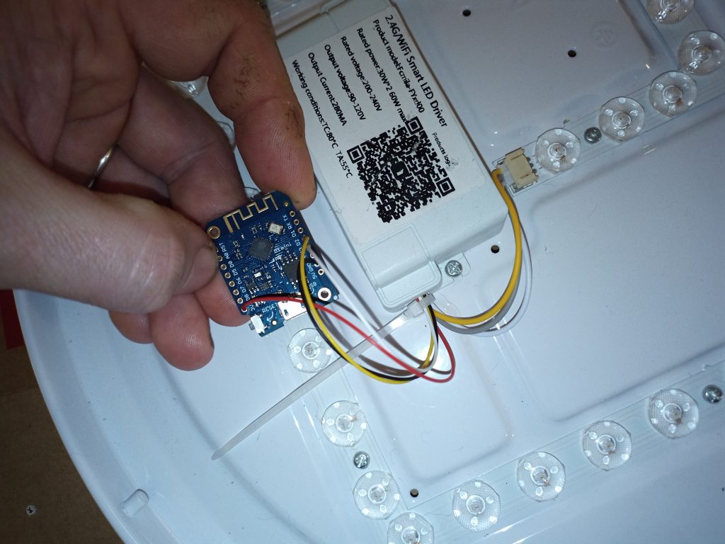
Now that we know where to get +3.3v and Gnd, and where to inject PWM, we can simply solder wires for power to pins 8 and 9, and PWM signals to 4 and 5.
Take whatever code you want that does PWM, apply it to Wemos pins D2 and D3, flash it to the board, and then disconnect and power up from the mains supply.
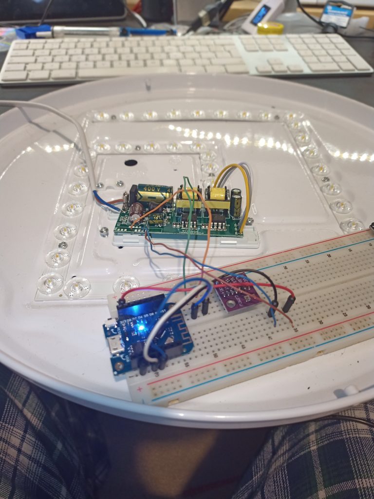
Since I use ESPHome, after a few moments the device was online and had a webpage available. Another few clicks of the autodiscovery feature in Home-Assistant had the newly found light integrated into the rest of the home automation system.
Code can be found at https://github.com/kylegordon/home-assistant-config/tree/master/esphome
The picture below is the mostly finished item. One more cable tie, a bit of hot glue, and it’ll be ready to go with its new, locally controlled, ESP8266 brain.
Recent Comments