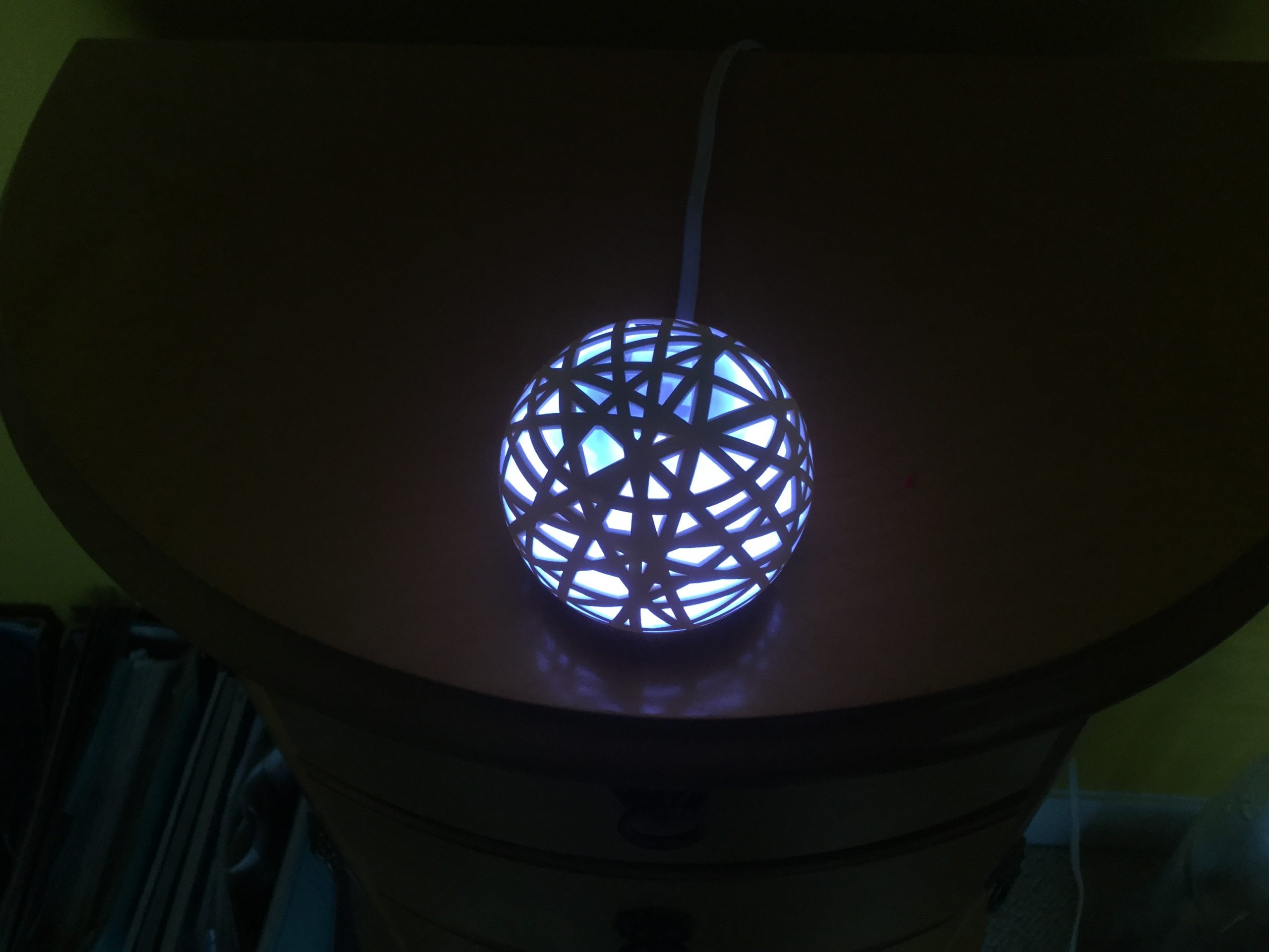
A long time ago, I was a Kickstarter supporter of the Hello Sense. It was a ball shaped thing that could sit on the bedside cabinet, and would report on noise levels, air quality, and light level. It would also act as a hub for little Bluetooth Low Energy sensor ‘pills’ that would clip to your pillow to tell you how much you moved when sleeping. It would also use that data to trigger the morning alarm at an appropriate point of your sleep cycle, rather than screaming at you in the middle of a deep sleep.
All in all, my wife and I actually found it to be a really nice device.
Sadly, the company failed to sustain itself, and in mid 2017 the company shut down. Since the device was heavily internet reliant, it lost all the functionality. Even though they published much of the codebase on https://github.com/hello/ it was never picked up on by enthusiasts.
I kept the hardware around as, quite frankly, it was excellently made and I had a little (unfounded) hope that the server side of things could be resurrected. In the end that didn’t happen, and I discovered inside the Sense globe was a ring of WS2812 individually addressable LEDs.
We both liked the idea of a Cheerlights driven Glow Orb, and so I set about opening it up and converting it. I decided to power it using the existing USB socket since it’s a custom moulded USB plug that fits into a matching hole in the base of the globe. Internally, it would have a Wemos D1 Mini ESP8266 microcontroller, running ESPHome so that it could be connected to our Home-Assistant home automation platform.
Here are the notes I hastily typed whilst working on it.
Remove the sticky base from the bottom of the Sense to reveal four screws.
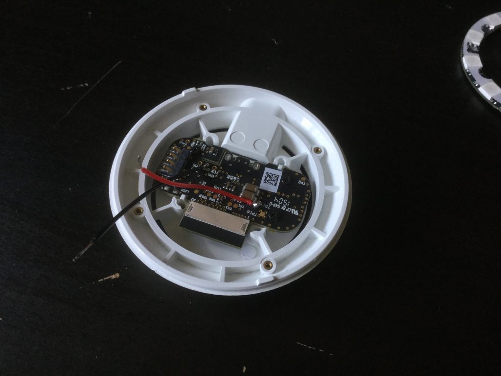
Remove the screws and remove the base of the Sense. This will reveal the PCB and USB socket. Gently pull the ribbon cable out of the base PCB to detach it completely.
Unscrew the LED ring from the base, and keep safe both the screws and ring. The screws for the LED ring are of a different size from the other *tiny* screws, so keep them separate.
Unscrew the electronic PCB from the bottom base, and also keep the screws and PCB safe.
You should now have a disassembled base unit, and the remains of the globe rolling around in one piece.
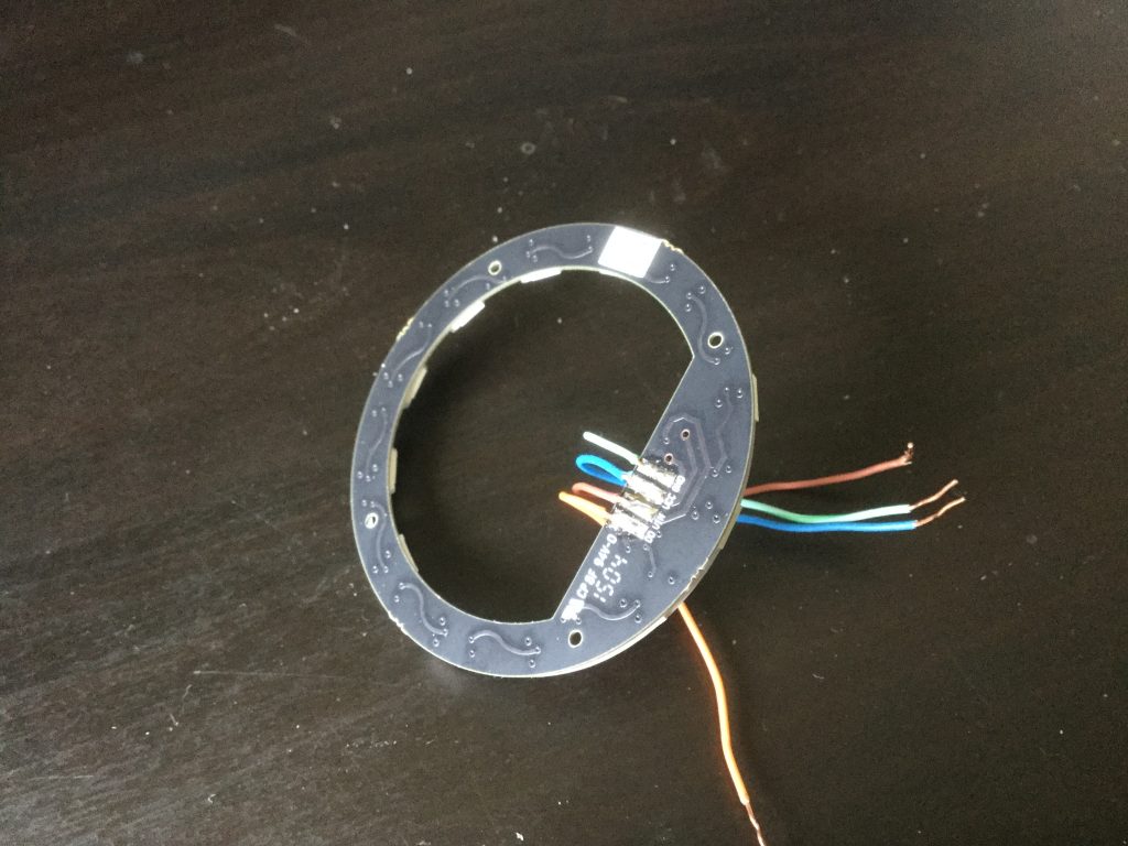
The LED ring is a solid ring PCB with 12 WS2812 individually addressable LEDs. We can reuse the whole thing by soldering wires onto the Vcc, GND and Vin pads. If you’re interested the schematic for the LED ring can be found at https://github.com/hello/morpheus-board-led/blob/96af86fde05a6ef1c74da56750172f232244f251/Release%20Files/Morpheus_LED_PVT_release_123014.PDF (also attached).
It looks like Hello slightly mislabelled the PCB, and what is written as VIn is actually DI. DO (Data Out) is labelled correctly, but don’t read it as D0 (Data Zero) like I did for far too long. You will want to solder some nice flexible wires to VIn, Vcc, and GND. You can start testing the ring and experimenting with WS2812 support in your favourite micro-controller now if you like.
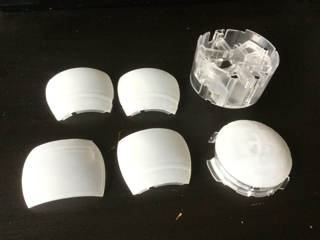
You can now remove the main core of the Sense. I think you’re supposed to be able to slide it out from the ‘acoustic mesh’ surround, but I found I had to rotate it inside the orb and remove each mesh panel separately. They just unclip from the clear plastic core. This is slightly fiddly, and I find working to lift one side of the panel up and then pulling it away and downwards seems to help.
The clear plastic core is used as lightpipes, so we’ll be reusing the plastic to diffuse the light around the orb.
Once the core is out, unclip the clear top PCB carrier, unclip the top mesh, unscrew the PCB and dispose of it. Be sure to keep the top PCB carriers.
You can then do similar with the rest of the core. You can dispense with the main body PCB as well, but the Sharp GP2Y10 fine dust sensor module in the middle might come in handy for future projects.
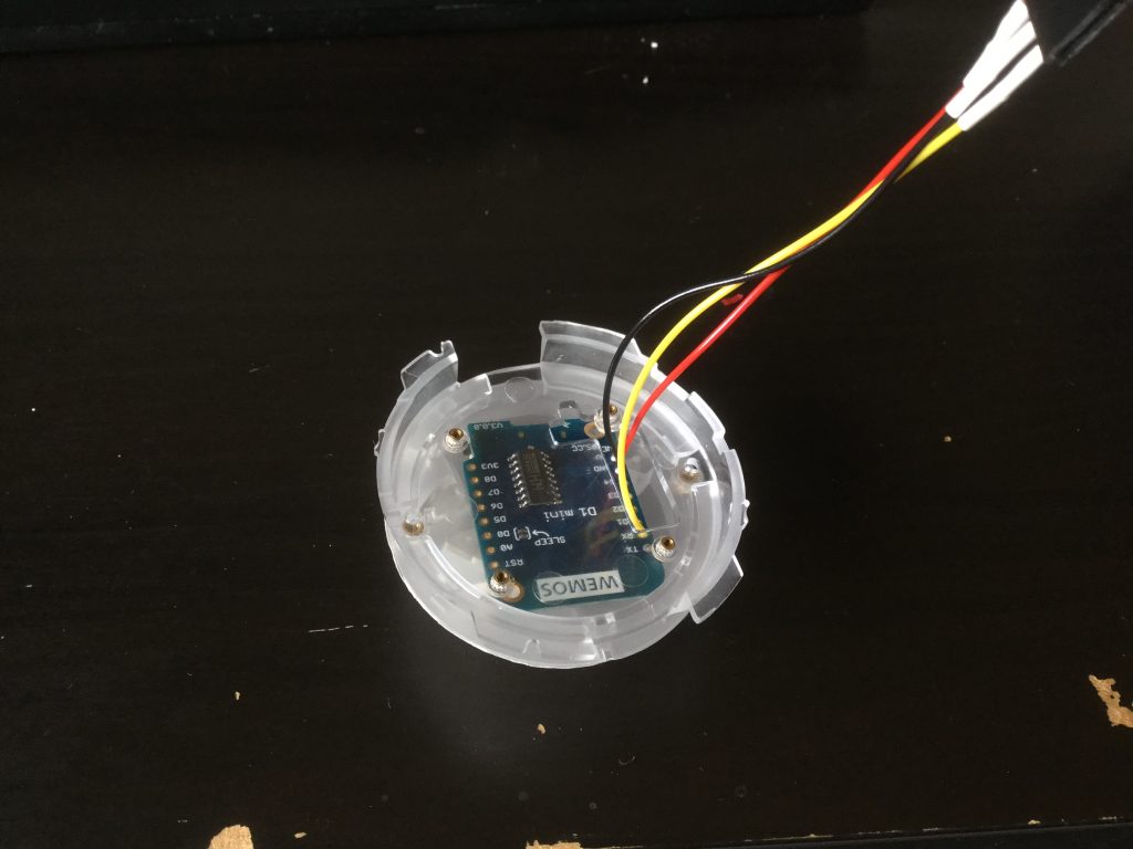
I wanted to use a Wemos D1 Mini to drive the LEDs, so I could control it using MQTT or Home-Assistant. Since it’s a bit big to fit with connectors through the gaps at the bottom of the core, it will need installed into one of the layers inside the core, with some wires dangling down. I decided to place it on the very upper layer, with the status LED facing upwards. The LED would normally be dark, but by making it slightly visible it can be used as a status LED, and will flash if not connected to Wi-Fi.
To save some assembly headaches, I also opted to also put a little connector on the wire at the bottom end of it. You will need three wires, connected to +5v, GND, and GPIO3 (aka, RX on the Wemos D1 Mini). GPIO3 is the default for ESPHome to drive WS2812B LEDs as a NeoPixelBus device, as per https://esphome.io/components/light/neopixelbus.html
Now would also be a good time to install some software that you can later update wirelessly, like ESPHome or Tasmota.
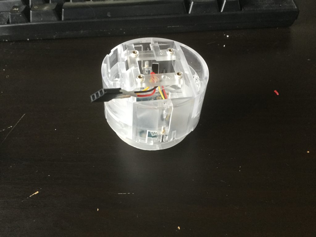
You should now be able to put the Wemos inside the top layer, thread the wires through the core, screw the core back together, and temporarily tuck the connector of the wires inside the bottom of the core. Use hot glue or a cable tie to hold it down and stop it rattling around. Ensure the cable comes out from the bottom through the larger opening at the side. This way it should give the other cables some space to flex and move around. At this point you can also put in the two long screws to hold the core together.
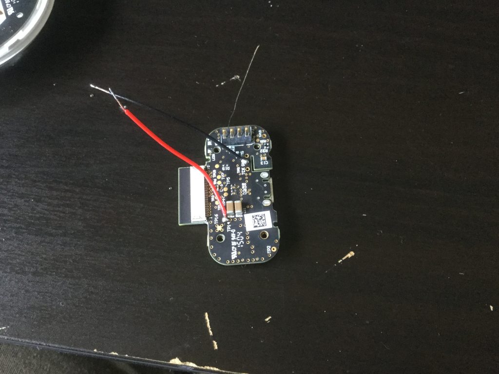
Now comes the tricky bit – the base. Take the little PCB that you saved from the baseplate, and find TP14 and GND. TP14 is ‘Test Point 14’, and GND is one of the through hole points for the JTAG interface (neighbouring pins include TCK and TMS). Solder on small wires to GND and TP14 – long enough that they’ll reach the pins on the LED ring. GND will go to GND, and TP14 will go to Vcc. Due to the size, this solder connection may be a bit fragile, so it might be worth soldering them to the larger LED ring pads first.
When placing the LED ring in a position for wiring and attaching back to the base, make sure to ROTATE it 180 degrees so that the spring loaded pads on the base PCB no longer contact the LED ring. This is is the key to being able to use the built in USB connector for powering it all.
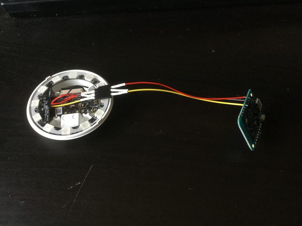
Once TP14 is wired to Vcc, and GND to GND, you should now have something similar to the picture, where both the base PCB and the ESP8266 are wired to the LED ring. Also in the picture is the little connector that allows the ESP8266 to be disconnected, installed inside the core, installed inside the Orb, and then plugged in when the base is ready to go on.
So it now has a mostly assembled base, and a mostly assembled core. It’s time to make sure the top PCB carrier is still clipped on, and then fit the top acoustic mesh, insert into the Orb casing, and clip on the side acoustic mesh panels. Putting on the side panels seems to be done one at a time, and rotating the unit inside the Orb casing. It’s *very* fiddly and infuriating, and sometimes it seems you have to press on it very hard whilst trying to slide the panel down into the little groove on the core.
Eventually, you will end up with the fully assembled core and acoustic mesh panels sliding around inside the globe. Rotate and adjust the core until the panel joins are hidden by the vertical lines on the outer globe. Now carefully plug the base unit into the loose connector that comes down from the Wemos. The casings will also need rotated so that the keyed slots meet together correctly, and then it can be held firmly together whilst the 4 screws are inserted and screwed in.
Now that it’s all assembled and back in one piece, plug it in to USB power and it should power up and start the firmware that you loaded onto it. In our particular case, it runs ESPHome and connects to our Home Automation system. The code that I have running it is stored here
https://github.com/kylegordon/home-assistant-config/blob/master/esphome/common/sense_gloworb_common.yaml
https://github.com/kylegordon/home-assistant-config/blob/master/esphome/sense_gloworb_1.yaml
Recent Comments